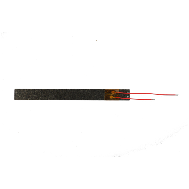
What is a Mica Heating Element?
A mica heating element is an electrical Heating Device that utilizes mica as both an insulating and supporting material for its resistance wire. These elements consist of nickel-chromium (NiCr) or iron-chromium-aluminum (FeCrAl) alloy resistance wires (tyPIcally 80/20 NiCr or Kanthal A-1 alloys) sandwiched between layers of high-quality mica sheets (muscovite or phlogopite mica with dielectric strength of 2000-3000 V/mm). The mica layers provide excellent electrical insulation while allowing efficient heat transfer, with thermal conductivity ranging from 0.35 to 0.70 W/m·K perpendicular to the cleavage plane.
Key technical specifications of mica heating elements include:
Operating temperature range: -50°C to 500°C (continuous), with peak temperatures up to 800°C
Power density: 1.5 to 5 W/cm² depending on configuration
Thermal response time: 30-90 seconds to reach operating temperature
Dielectric strength: ≥2500 VAC at 1mm thickness
Surface leakage current: <1 mA at rated voltage

Characteristics of Mica Heating Elements
1. Rapid Thermal Response: The thin construction (typically 1-3mm thickness) and low thermal mass enable mica heaters to achieve 90% of their rated temperature within 60 seconds, significantly faster than ceramic or Tubular Heaters.
2. Uniform Heat Distribution: The planar design with precisely spaced resistance wire patterns (wire spacing tolerance of ±0.2mm) creates surface temperature uniformity within ±5°C across the heating area when properly installed.
3. High Efficiency: Mica's low thermal conductivity perpendicular to the cleavage plane (0.35 W/m·K) minimizes heat loss to the mounting surface, achieving 85-92% thermal efficiency in typical applications.
4. Mechanical Stability: The layered construction maintains dimensional stability with linear expansion coefficient of 8-12 × 10⁻⁶/°C, preventing warping even under rapid thermal cycling.
5. Electrical Safety: Mica's high dielectric strength (2000-3000 V/mm) and volume resistivity (10¹³-10¹⁵ Ω·cm) ensure safe operation even in humid environments (up to 95% RH non-condensing).
Application Scenarios
Industrial Processing: In plastic injection molding machines, mica heaters maintain barrel temperatures of 150-400°C with ±2°C control accuracy. The 3-5 W/cm² power density enables rapid recovery after material changes.
Food Service Equipment: Commercial griddles utilize mica heating elements to achieve surface temperatures of 200-300°C with response times under 45 seconds, while the moisture-resistant construction withstands daily cleaning cycles.
Medical Devices: Blood analyzers employ low-voltage mica heaters (24V DC systems) to maintain 37±0.5°C incubation temperatures, leveraging the elements' EMI-free operation for sensitive instrumentation.
Aerospace: De-icing systems in aircraft use mica heating elements capable of -50°C cold starts and 300°C operational temperatures, with power-to-weight ratios of 1.8 kW/kg.
Laboratory Equipment: Analytical instruments require the contamination-free heating provided by mica elements, which exhibit outgassing rates below 1×10⁻⁶ Torr·L/s·cm² in vacuum applications.
Maintenance Procedures
1. Cleaning: Use only isopropyl alcohol (≥70% concentration) with lint-free wipes. Avoid abrasives that could damage the mica surface (surface roughness should remain ≤3.2 μm Ra).
2. Inspection: Monthly visual checks should verify:
No visible discoloration (localized temperature variations >50°C may cause color changes)
Wire spacing uniformity (maintain original ±0.2mm tolerance)
Insulation resistance (≥100 MΩ at 500VDC when measured cold)
3. Electrical Testing: Quarterly megohm testing should show insulation resistance >50 MΩ at operating temperature. Power input should not deviate more than ±10% from nameplate rating at rated voltage.
4. Mounting Surface Maintenance: Ensure flatness within 0.1mm over any 100mm length to prevent hot spots. Apply fresh thermal compound (thermal impedance ≤0.05°C·cm²/W) during reinstallation.
5. Storage: When not in use, store in 40-60% RH environments with protective covers. Avoid stacking more than 10 elements to prevent deformation.
6. Performance Verification: Annually verify temperature distribution using infrared thermography or surface probes, ensuring no area exceeds ±15°C of setpoint under stabilized conditions.


